The trolley track hoist is the type of hoist most commonly used by built-up roofing crews. Trolley track hoists come in two sizes designated by one manufacturer as the TT400 and the TT1000. These two numbers indicate the maximum weight capacity (in pounds) of each hoist.
Note: Read, understand, and follow the written manufacturer’s instructions for the assembly and operation of all equipment, including hoisting equipment. The assembly and/or operating instructions for your equipment may differ from that described herein.
The following typical assembly and operating information refers to a mechanically driven Trolley Track Hoist system. Many Trolley Track Hoist systems now use hydraulic motors driven by gas or diesel engines to drive the winch with attendant modifications to assembly and operating instructions.
Assembly
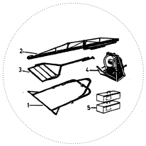 Both sizes of trolley track hoists have five main components:
- Front Frame Assembly
- Trolley Rail
- Rear Leg Assembly
- Power Unit
- Counterweights (never use materials)
Using a gin pole (hoist beam) and hoisting wheel, or other suitable method, bring the rear leg assembly up to the roof and place it at least 7.6 m (25 ft) back from the roof edge. Bring the front frame assembly up to the roof and place it approximately 4.3 m (14 ft) in front of the rear leg assembly. Finally, bring the trolley rail up to the roof and position it between the front and rear leg sections. Ensure that all three components have been laid out at least 3 m (10 ft) back from the roof edge. It should typically take three workers about twenty minutes to assemble a trolley track hoist and have it in place, ready to begin work. No tools are typically required as the components are held together with self-locking pins.
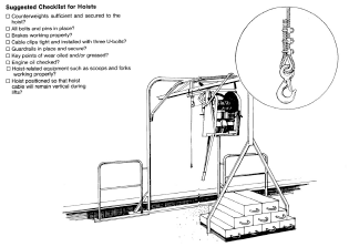
The instructions for assembly, operation and dis-assembly the typical Trolley Hoist brand shown in the attached illustration read as follows:
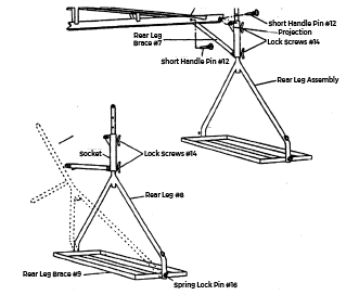
- Remove Spring Lock Pin #16 on the Rear Leg Brace #9 and raise the Rear Leg #8 to an upright position.
- Move the socket on the Rear Leg #8 to its lowest position by releasing the Lock Screw(s) #14 and retighten.
- Slide the Rear Leg Brace #7 into the Trolley Rail assembly (rear).
- Raise the Trolley Rail assembly over the projection at the top of the socket on the Rear Leg #8 and attach with a Short Handle Pin #12 through the matching holes in the Trolley Rail assembly and the socket projection.
- Pin the Rear Leg Brace #7 to the Trolley Rail assembly with a Short Handle Pin #12 through the matching holes.
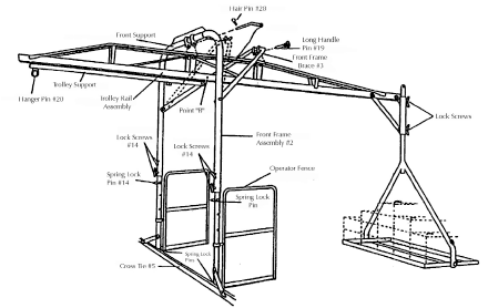
- Raise the Front Frame Brace #3 and tie temporarily to the top of the Front Frame #2.
- Release the Spring Lock Pins holding the Operator Fence(s) and swing fences 90° to help support and brace the front frame during assembly.
- Raise the Trolley Rail assembly and secure to the Front Frame assembly Handle Pin and Hair Pin #28 through the matching holes in the Front Support of the Trolley Rail assembly and the Front Frame #2 Pin Tabs.
- Untie the Front Frame Brace #3 and secure to the Trolley Rail assembly with a Long Handle Pin #19 through the matching holes in the Trolley Rail assembly rear support.
- Swing the Operator Fence(s) outward to their protective wing positions on either side of the Front Frame assembly and pin into place with a Spring Lock Pin.
- To adjust the height of the Trolley Rail assembly raise it on both the Front Frame Legs and the Rear Leg until it is in the desired position (generally at maximum height). Insert Pins into each leg (front and rear), lower Front Frame and Rear Leg Socket to rest on Pins and tighten Lock Screws #14.
NOTE: If not using the track at its maximum working height insert Pin above socket on rear leg. The trolley rail should be slightly lower than the rear leg to facilitate pulling loads.
- Carefully move the entire unit to the edge of the roof carrying the Front Frame from the inward side and also carrying the Rear Leg assembly. The Front Frame assembly should be as level as possible, resting on a secure base at the roof edge. Holes are provided in the Cross Tie #5 so it can be fastened to a 600 mm x 1800 mm (2 ft x 6 ft) plank, or 1200 mm x 2400 mm (4 ft x 8 ft) plywood.
- Load the counterweights on the Rear Base #9. Make certain they are properly nested. Tie the counterweights securely to the D Rings on the Rear Leg assembly to prevent accidental removal. (Counterweight must be one and a half times the maximum load weight.
- As an additional precaution, attach the stay wire to a suitably fixed object on the roof.
- Tighten all Lock Screws and make sure Lock Pins are inserted.
Mounting the Power Pack
Once the trolley track hoist has been assembled and moved into place, attach a hoist wheel and rope to Hanger #20 at the end of the trolley support. Lock the trolley out by putting pin #12 through the rail at Point “B”.
Attach the rope securely to the frame of the power pack unit and raise the unit up to the roof. At least two persons will be required to hoist the power unit to the roof. Remove the lock pin from the track and pull the power unit into the extreme rear end of the track. Replacing the pin through Point “B” will prevent the power pack from rolling forward.
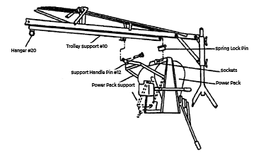
Carefully lower the power unit to the roof.
Before mounting the power unit, ensure that the trolley is rolled to the back of the hoist and locked in place with a pin through Point “B”. This will ensure that the trolley is stable during the mounting procedure. The power pack unit can weigh between 92 kg (203 lb) and 100.6 kg (222 lb). Depending on the model being used it may require as many as four persons to lift the unit into place.
Lift the power unit so that the socket provided in the power slides onto the end of the trolley support. Secure with a clip #16. Swing the power unit support up into place on support and secure with pin #12.
Operating the Hoist
The power pack unit is equipped with three handles that control the lifting and lowering of the loads. The handles are locked into an upright position against the frame of the power unit for shipping. The handles can be placed in any of three positions and locked in place using a clip pin, for the convenience of the operator.
- The brake handle is located on the This handle is used to lower the load.
- The clutch handle is located in the This handle is used to hoist the load.
- The stabilizing handle is located on the This handle is used to stabilize the power unit during either the hoisting or lowering of all loads.
Hoisting
Before the hoisting operation can begin the engine should be started and allowed to warm up.
- Engage the pawl on the ratchet and pawl assembly in addition to the automatic holding brake. A ratchet and pawl are supplied. Engaging it holds the load in place and prevents the load being lowered even if the brake lever is raised by mistake.
- Increase the speed of the power unit.
- The brake is released automatically as the clutch handle is lifted and the load is raised.
- When the load has reached the roof level, release the clutch handle, this will automatically engage the brake and hold the load in place.
- Using the stabilizer handle pull the load onto the roof, and reduce the engine speed to idle.
Lowering
- Disengage the pawl (never engage the pawl while lowering any loads). Should the pawl be difficult to disengage because of pressure, raise the load slightly to relieve the pressure and then disengage the pawl.
- To release the brake, raise the brake handle and lower the load.
- Lowering the brake lever applies the brake and decreases the lowering speed. As the load is lowered, it will be important to vary the position of the handle, so as to maintain a safe, controlled lowering speed.
- Never jam on the brake. Always raise the brake handle slowly, keeping the lowering speed under control.
Dismantling the Trolley Track Hoist
Move the entire hoist back away from the roof edge.
Rear Leg Assembly
- Disconnect stay wire (if attached).
- Remove Counterweights.
- Remove pins and loosen Lock Screws #14 and lower unit on the leg.
- Disconnect Trolley Track Assembly from Rear Leg Brace #7 and Socket Projection.
- Lift Trolley Track Assembly to the roof.
- Lower Rear Leg and pin into shipping position.
Front Frame Assembly
- Move Operator Fence(s) to 90° position so they will support Front Frame assembly.
- Remove Lock Pins from legs.
- Loosen Lock Screws #14 and carefully lower frame on the legs.
- Disconnect the Trolley Rail assembly by removing Handle Pins #19 from Frame and Front Frame Brace #3. Lower Trolley Rail assembly to the roof.
- Reposition Operator Fence(s) and re-pin in shipping position.
Be Safe:
Carefully move the individual sections over the roof edge and deliver them to the ground.
Ensure all personnel involved with hoisting wear head and hand protection at all times.
Routinely inspect bolts and pins, cables, brake ropes, counter weights, rigging slings, hooks and shackles.
Before lifting a load, make a “dry run” to ensure the hoist is operating properly and you are familiar with the controls.