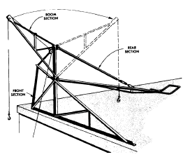
Using A-frame structures for hoisting goes back many years. A counterweight is used to balance the leverage of the load that is being raised. When the hoist beam is hinged, it becomes a swing beam that allows the load to be spotted directly on the roof.
As smaller engines were developed, they were put to use on the ground, keeping the power unit stationary at all times. More recently the ability to pack more horsepower into smaller engine blocks allowed the power plant to be moved from the ground and installed directly on the beam of the hoist.
Note: Read, understand, and follow the written manufacturer’s instructions for the assembly and operation of all equipment, including hoisting equipment. The assembly and/or operating instructions for your equipment may differ from that described herein.
The following typical assembly and operating information refers to a mechanically driven Swing Beam Hoist system. Many Swing Beam Hoist systems now use hydraulic motors driven by gas or diesel engines to drive the winch with attendant modifications to assembly and operating instructions.
Typical Assembly
The main frame of the hoist should be assembled at least 3 m (10 ft) from the edge of the roof. It should typically take three workers about twenty minutes to set up the hoist and have it ready to start work. The only tools needed to assemble the hoist are two 300 mm (12 in) crescent wrenches and one hammer.
The hoist can be assembled in the following order.
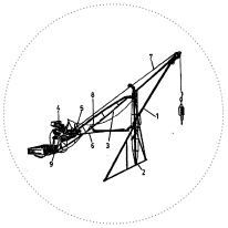 A-frame tower (2)
- Main boom (3)
- Power pack (4)
- Winch (5)
- Swing arm (1)
- Cable (7)
- Hoist control rod (6)
- Brake chain (8)
- Clutch (9)
Once the main frame of the hoist has been assembled, all nuts, bolts and pins should be checked to ensure they are tight. Move the hoist to its permanent hoisting position and ensure that the A-frame is on a level surface.
Final Assembly
Mount the cable drum unit into place on the main beam. The platform on the beam and the drum frame has four pre-drilled holes. Line the holes up, dropping the bolts through the hole and then tighten the nuts. The cable drum is now securely in place. Two people may be required to set the drum in place as it weighs approximately 64 kg (140 lb). Mount the Gas Power Pack behind the cable drum unit, with one person each lifting each side of the motor and lining the power pack platform up with the slot provided in the main beam. A third person secures the power pack platform to the hoist with a clevis pin and a clip through both the slot on the main beam and the power pack platform.
Both the power pack and the cable drum unit are equipped with two sprockets each, one large and one smaller, and a drive chain (much the same as the one used on a bike). The chain and sprockets transfer power from the power pack to cable drum.
Below the power pack platform is an adjusting screw that allows the platform to be raised or lowered. The platform is raised to allow the drive chain to be placed over the sprockets and then lowered until the chain is tight. The chain should have about 12.7 mm (1/2 in) of play in it.
Once the power pack and the cable drum unit are in place, thread the cable through the swing arm. Make sure the swing arm is in all the way and have one worker bracing the boom. Use a step ladder to thread the cable through the top of the swing arm. The cable can be released by pushing down on the brake lever.
Hoist Operation
The cable drum unit is equipped with a clutch and a brake. The brake is controlled by a chain that has one end connected to the brake lever and the other end is connected to the hoist near the top of the A-frame tower, hanging down loosely within easy reach of the operator. A light pull on the chain releases the brake allowing the load to be lowered.
The brake is a one-way brake, (i.e. a brake that is always engaged unless there is pressure applied to the brake chain).
The clutch is controlled by a long handle that fits right into the clutch assembly. A slight pull on the control engages the clutch starting the hoisting operation. Twisting the control handle can adjust the hoisting speed. Pushing the control arm out will disengage the clutch stopping the hoisting operation. The load will be held in place by the one-way brake. Once the load has been hoisted to the roof light pressure on the boom release latch automatically swings the load in onto the roof. Slight pressure on the brake chain will deposit the load right on the deck.
To return the hoist cable to the ground, swing the boom back into the latched position. Pushing down on the brake allows the cable to return to the ground. A cable return weight that slips over the hoist cable hook can be used to speed up this process.
Hoist Take Down
Thread the cable back through the swing arm. Engage the motor and rewind all excess cable back onto the cable drum. This can also be done by hand using the winch handle that is part of the hoist. Allow the power pack to cool off, and then remove the power pack and the cable drum unit from the hoist beam. Attach a hoisting wheel and rope to the swing arm and lower the drum cable unit and the power pack to the ground.
Move the hoist frame back at least 3 m (10 ft) from the roof edge and disassemble the hoist. Using a gin pole (rigid beam hoist), lower the hoist frame components to the ground.
Hoist Operator’s Checklist
- Read all manufacturer’s instructions before operating the hoist.
- Check the hoist frame to make sure it is in good shape and has not been bent or damaged on previous jobs.
- Hoist should be set up on a flat level surface.
- A-frame tower is secured and weighted, if necessary.
- The cable is in proper working order with no weak spots or frays.
- All nuts, bolts, clips and pins are tight and secure.
- The material to be hoisted is directly below the hoist.
- There is 45.4 kg (100 lb) of permanent counterweight for every 90.7 kg (200 lb) of material being hoisted (one half times the load). Never use roofing material as a counterweight.
- A fire extinguisher is available on the roof close to hoist.
- Bolts holding the power pack and the cable drum unit are tight.
- The hoist area on the ground is clear of people and a warning barrier has been set up.
- All personnel involved with the hoisting of material have adequate head protection.