Once the membrane has been installed and the laps seamed, the membrane flashings can be installed. All flashings must extend up walls a minimum of 200 mm (8 in) and on to the horizontal membrane at least 75 mm (3 in).
Always use the longest flashing lengths possible. Install membrane flashings as follows:
- Bond the membrane flashing to the field membrane as with the lap seaming procedure.
- Once the flashing membrane has been bonded to the field membrane, roll it back and apply the bonding adhesive to the wall on inside and top of parapet. Apply bonding adhesive to both mating surfaces where directed by the membrane system manufacturer.
- Once the bonding adhesive has dried until it is tacky to the touch (or as otherwise directed) carefully roll membrane up wall (or parapet). Firmly press it along the base and work up the wall.
Gravel Stops & Roof Edges (Using Tape)
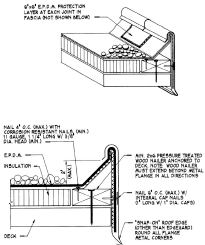 Install the field membrane over the roof area. Ensure that the field membrane extends beyond the edge of the roof at least 75 mm (3 in).
- Turn down the membrane over the edge. Seal bottom edge of membrane with general purpose sealant or fully adhere the membrane to outside face of wood blocking with bonding adhesive.
- Nail membrane to outside face of wood blocking with 9.5 mm (3/8 in) diameter head galvanized roofing nails at 150 mm (6 in) o.c.
- Install metal gravel stop or other edge detail. Nail gravel stop flange at 100 mm (4 in) o.c. with galvanized nails, placed approximately 19 mm (3/4 in) from the edge of the flange.
- Remove dust and talc from edge area with a stiff broom. Clean the metal and membrane with splice cleaner.
- Place the roll of flashing tape a few feet ahead of the application starting point (with release paper on top).
- Apply splicing primer adhesive in the same fashion as at a seam.
- Remove 600 or 900 mm (2 or 3 ft) of the release paper and apply the tape to the flange of the metal, lapping onto the field membrane at least 50 mm (2 in).
- With a hand roller, roll the flashing tape to ensure proper adhesion.
- Apply lap sealant as required by the membrane manufacturer.
Roof Drains
The following are the application procedures for cast iron drains:
- Provide a clean and even finish on the mating surfaces between the clamping ring and the drain bowl.
- Taper the insulation around the drain to form a sump. (Use pre-manufactured tapered insulation with facers suitable for bonding the membrane in adhered systems).
- Position the Thermoset membrane over the drain and cut a hole for the drain. Allow 25 mm (1 in) of membrane to extend inside the clamping ring past the drain bolts.
- Make round holes in the membrane to align with the clamping bolts. Do Not cut the membrane back to the drain bolts.
- Place approved sealant on top of the drain bowl where the clamping ring sits on top of the membrane.
- Install the roof drain clamping ring and clamping bolts. Tighten bolts to achieve proper compression.
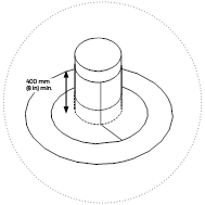
Pipe Flashing
 Most manufacturers supply pre-moulded pipe boots that can be cut to the height and size of opening to suit the pipe. These are formed out of butyl or thermoset and usually come with splice tape laminated to the bottom flange of the boot. To install a pre-moulded pipe boot:
 Select the pipe flashing that will accommodate the outside diameter of the pipe to be flashed.
- Apply the splice primer/adhesive to the area on which the flange will sit as you would with a seam area. Ensure that this area is cleaned thoroughly with splice cleaner before applying the adhesive.
- Position the boot over the pipe.
- Remove the release paper from the bottom of the flange.
- Mate the pipe flashing flange to the prepared Thermoset and roll with a hand roller.
- Install lap sealant and stainless-steel clamping ring to the pipe as directed by the membrane system manufacturer.
Field Fabricated Pipe Flashing
In some cases, a pre-moulded pipe boot is not available or cannot be installed over an existing fitting. In this instance, pipes may be flashed using uncured flashing membrane. The procedure is as follows:
Step 1
 Cut a piece of flashing membrane so that it extends at least 75 mm (3 in) onto the field membrane in all directions.
- Position the flashing piece over the pipe and mark the center of the opening.
- Cut the membrane in an X, slightly smaller than the size of the opening.
- Apply splice primer/adhesive to the cleaned field membrane and on to the outside of the pipe.
- Pull the pipe flashing over the pipe and set on to the field membrane. Roll the flashing firmly with a hand roller.
Step 2
 Cut a strip of flashing membrane that is wide enough to extend on to the roof at least 50 mm (2 in) and up the pipe 200 mm (8 in). Allow for an overlap of 50 mm (2 in) minimum.
- Apply splice adhesive to the top of the previously installed base flashing and sides of the pipe flashing.
- Wrap the strip flashing around the pipe. Firmly press the bottom flange of the flashing to the previously applied base flashing and on to the pipe.
- Roll membrane flashing firmly with a hand roller.
- Apply lap sealant at all exposed edges of the membrane flashing, including the edge against the pipe.
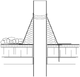
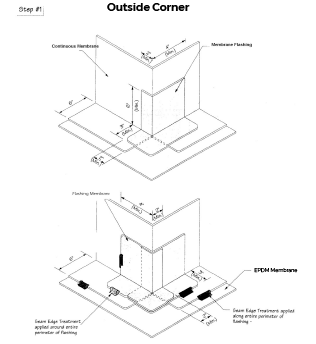
Inside and Outside Corners
For flashing inside corners, it is suggested field membranes be used to bridge the roof- to-wall transition to provide a continuous wall flashing. Membrane adhesive should be applied inside the trimmed corner fold and the fold secured flush against the wall with adhesive. The area should be cleaned using EPDM primer. A pre-cut self-adhering flashing should be adhered to completely cover the fold and provide a lap of at least 75 mm (3 in) or in accordance with manufacturer recommendations. Flashing edges should be sealed with lap sealant as required by the manufacturer.
Outside corners should be fitted with two pieces of membrane. The membrane should be a minimum of 200 mm (8 in) long and wide enough to extend up the wall 200 mm (8 in), and lap over the main membrane 75 mm (3 in). Position the membrane so that a minimum 50 mm (2 in) is folded around the corner. Clean and seal in place with splice adhesive. Install the second piece of membrane on the other side of the corner. Apply lap sealant along all joints.
Inside Corner
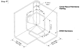
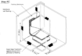
Alternatively, premoulded and pre-taped inside and outside corner flashings may be available for use at these locations.
Metal Flashings
When a drip edge or gravel stop flashing is required, it must be fastened 100 mm (4 in) o.c. to the nailer in a staggered pattern. Over this install a layer of membrane flashing wide enough to cover flange and replace with lap main roof a minimum width of 75 mm (3 in). Seal with splice adhesive and lap sealant. Alternatively, install a self-adhering cover strip.
Install all metal counter and cap flashings, ensuring that no sharp edges or corners are in contact with the membrane.