The ladder hoist is most commonly used by steep slope roofers, as most are not suited for moving gravel. It is a very fast, time efficient way to move smaller, lighter loads to the roof. It should be noted that it is the most dangerous because the operator stands under the load. Use extra caution.
Note: Read, understand, and follow the written manufacturer’s instructions for the assembly and operation of all equipment, including hoisting equipment. The assembly and/or operating instructions for your equipment may differ from that described herein.
A typical Ladder Hoist System includes an aluminum ladder that is equipped with a skip, which runs up and down the ladder sections, powered by a small stationary gas or electric power unit located at the bottom of the ladder.
The ladder comes in three sections; 4.9 m, 2.4 m, and 1.2 m (16 ft, 8 ft, and 4 ft) allowing the hoist to reach a maximum height of 13.4 m (44 ft). The ladder sections are joined with a sleeve fit (male to female ends) between the sections or a splice plate permanently joined to upper extension ladder sections with bolts and lock nuts. No special tools are required, just 200 mm (8 in) crescent wrenches.
The typical ladder hoist comes in three types:
- Heavy duty, capable of hoisting up to 181 kg (400 lb).
- Medium duty hoists capable of hoisting up to 114 kg (250 lb).
- Light duty hoists capable of hoisting up to 90.7 kg (200 lb).
The ladder is placed against the building ensuring that the base of the ladder is 1/4 to 1/3 of the height in distance away from the wall.
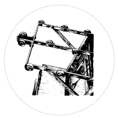 The power unit is hung on a rung at a convenient height and clamped in place using a quick acting positive latch, run the cable up the back of the ladder, through the pulley at the top and down the front of the ladder and attach it to the carriage.
Running the Hoist
The power unit is equipped with two handles; the clutch lever for raising loads and the brake lever for lowering loads. Raising the clutch lever engages the load carriage and releases the brake. Releasing the clutch applies the brake automatically. 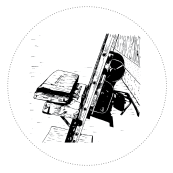 Raising the brake lever will release the brake. Minor adjustments may be required to the height of the brake lever while raising the brake to ensure a safe, controlled lowering of the load.
The carriage rides on ball bearing wheels that ensure the platform will not leave its track. The load also rides a wheel pressing it against a hinged gate. As it rides over the top of the track, the gate tips and the load slides onto the roof. Once the material is delivered, the gate follows the platform back down the track. A roller angle guide can be installed at the top of the hoist to help guide materials from the platform to the roof.