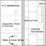
Thermoplastic membranes can be installed in either a conventional (where roofing membrane is installed on top of insulation) or protected membrane roof assembly (where roofing membrane is installed below insulation).
Thermoplastic membranes require caution during their installation. Careful attention should be taken to avoid damage or puncture of the membrane during application and correct welding of the seams is also critical to prevent water leakage.
There are three basic steps to follow when installing a thermoplastic roof system.
- Lay the membrane.
- Weld the seams.
- Install the membrane flashing (stripping).
7.1.3.1 Laying The Membrane
Loose-Laid Ballasted Systems
- Unroll the sheet and allow a minimum of 30 minutes for the membrane to relax and lie flat. Draw tight to remove folds or wrinkles. Use the largest pieces that are workable. Along parapet, walls and curbs, the sheet should typically extend 100 mm (4 in) up the wall or curb.
- Unroll the next roll in a similar manner. The new roll typically laps the previous roll a minimum of 75 mm (3 in). Manufacturer requirements shall be consulted for material specific lapping requirements.
- While welding seams, temporary weight may be required to hold the membrane in place, or alternatively the seam may be tack welded every 900 mm (36 in). Continue to lay remaining rows in same manner.
 Install perimeter fastening bars around perimeters and openings. Fastening bars generally consist of 25 mm (1 in) wide metal or plastic battens with pre-drilled holes for fasteners. Fasten bars into the roof deck or walls as per manufacturer requirements.
- Install strip flashing.
- Install ballast to completed areas as soon as possible to prevent wind uplift. Apply ballast at the recommended rate of approximately 60 kg/m² (1200 lb/square). In regions of high winds, additional ballast may be required.
Fully Adhered Systems
 Fully adhered systems are often used on projects which require light weight design, unusual shaped (domed, arched) or have special fire or wind uplift resistance requirements. Fully adhered systems can be used on decks with slopes ranging from flat to nearly vertical. However, because it is important that single ply membranes drain properly, it is recommended that the roof have a minimum slope of 1:50 (2%).
- The membrane rolls are set to run true with laps similar to those in loose-laid systems and as required by the membrane system manufacturer.
- Fold back the sheet one half of the sheet width and coat the underside of the sheet and/or surface of the deck or insulated with adhesive applied using the method and at the rate prescribed by the membrane manufacturer. Allow the adhesive to dry as required by the manufacturer for the adhesive type being used. Use only an insulation approved by the membrane manufacturer in an insulated system. Do not apply adhesive to the lap area. (If this occurs, remove the adhesive with appropriate cleaner in accordance with the manufacturer’s instructions.). Adhesive application rates and methods will vary depending on manufacturer, type of adhesive and whether smooth- backed or fleece-backed sheets are used.
- Carefully turn down the membrane on to the prepared surface and firmly press down. Press the membrane into place with a stiff push broom or steel roller to remove any trapped air. Turn back the remaining half width and repeat the same procedure. Install the remaining membrane in the same manner.
- Install perimeter fastening bars around perimeters and openings. Fastening bars normally consist of 25 mm (1 in) wide metal or plastic battens with pre-drilled holes for fasteners. Fasten bars in accordance with manufacturer instructions.
- Install strip flashing.
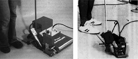
Non-penetrating induction fastening
- The coated metal plates and fasteners typically secure the insulation and/or membrane substrate and are distributed throughout the field in accordance with wind uplift design requirements supplied by the manufacturer.
- Position the membrane sheets over the installed fastening systems. Align the membrane edges in accordance with the sheet layout design and heat weld the seams in accordance with the membrane system manufacturers’ written instructions.
- Weld the underside of the membrane to the coated plates using the induction welding system. Adjust the welding equipment to accommodate for changes in temperature and membrane thickness as per manufacturer’s recommendations.
- Both seam welding and induction welding equipment settings should be calibrated using test welds at the start of each work period and after any significant changes in weather conditions during the work period.
- Side and end lap seams should not be located directly over coated fastener plates. Plates should not be located within 50 mm (2 in) from side and end laps.
Mechanically Fastened Systems
Mechanically fastened systems are often used on flexible decks which require lightweight design, where possible movement is expected to occur or on projects that have specific wind or fire resistance requirements. Mechanically fastened systems can be used on decks with slopes ranging from flat to nearly vertical. However, because it is important that single ply membranes drain properly. It is recommended that the roof have a minimum slope of 1:50 (2%).
- The membrane rolls are set to run true with the laps set as required to accommodate the installation of any in-seam fasteners as well as the seam sealing components. The sheet layout is typically provided in the membrane system manufacturers shop drawings and typically requires the sheets to be installed perpendicular to the roof deck so that the in-seam fasteners will spread wind uplift loads evenly to the deck and structure.
 Place metal/plastic battens or disks in the seams in strict accordance with the manufacturer’s requirements. Fasten battens, disks into the deck with approved fasteners. The spacing and fastening of the battens or disks will depend on the membrane manufacturer, local wind pressures, and the shape and size of the roof. Do not deviate from the manufacturer’s recommendations.
- After screws and disks are installed in the field of the membrane (outside of the seams), a cover strip is installed over the discs on to the roof membrane extending past the edges of the discs a minimum of 75 mm (3 in) in all directions or as required by the membrane system manufacturer. Weld the cover strip to the surface of the roof membrane.
- Install perimeter fastening bars around perimeters and openings as per manufacturer requirements. Fastening bars normally consist of 25 mm (1 in) wide metal or plastic battens with pre-drilled holes for fasteners.
- Install strip flashing.
7.1.3.2 Welding Seams
Only skilled workers, trained according to manufacturer’s specifications, are to weld the seams and laps. Laps are generally hand welded at flashing, terminations, or in small areas and machine welded where possible in the field of the roof.
Care must be taken with the welding process. If there is not sufficient heat to melt the membrane, a good bond will not occur. Too much heat will damage the membrane.
Hand Welding
Hand welding is performed in three stages. Before the hand welder is turned on, fit the welder with a 38 mm (1 1/2 in) wide nozzle for straight joints and 19 mm (3/4 in) nozzle for corner joints. Prior to starting, set the hand welder at the highest heat setting for at least one minute to preheat the nozzle. Adjust the heat output and complete test welds to confirm that the welder heat setting is appropriate for the material being welded and current work conditions.
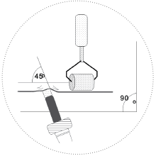 Weld the back-edge lap with a thin continuous weld bead to prevent hot air loss in the final welding process. Insert the nozzle between the lapped sheets to heat the area where the outside edge of the bottom sheet meets the top layer and press into contact with a hand roller.
- Insert the welder nozzle between the laps at a 45º angle. The correct temperature for welding is reached when the material begins to flow. At this point slowly slide the welder nozzle along the joint and at the same time use a hand roller to lightly press the two membranes together. The hand roller must be used at a 90º angle to the nozzle.
Automatic Welding (Machine welded)
Automatic welders are used in a similar manner to hand welders. The welding speed of an automatic welding machine is generally higher than that of a hand welder.
During the welding, look for these signs of a good weld which may vary depending on the membrane being welded. For PVC membranes, typical signs of a good weld include:
- A shiny membrane surface.
- Smoke development during welding.
- A continuous bead of melted membrane material from the joint.
Inspection of Seams
After cooling, all weld joints must be inspected for continuous bonding. A simple way of doing this is to slide a blunt nosed trowel or probe along the seam. If the trowel or probe lifts the lap, the area must be rewelded.
7.1.3.3 Flashing Installation
The materials and methods used to install the flashing (or stripping) will vary depending on the specific application. Although there are many possible applications, we will describe the three basic types of membrane flashing.
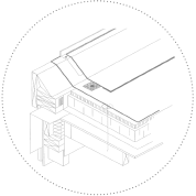
Drip Edge Flashing
This method is used with a typical gravel stop drip edge. In this method, the membrane is hot-air welded to the metal flashing. Whenever a PVC or TPO membrane is welded to metal flashing, metal coated with the same thermoplastic from the same manufacturer must be used.
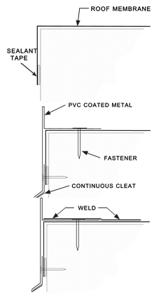 Before installing the flashing, apply a strip of sealant tape or compatible weather stripping at the outside perimeter just at the bottom of the fascia.
- Fit the membrane into position making sure that it exceeds the roof edge for a distance of the width of the outside fascia. Fold membrane over the edge and press firmly into the sealing strip.
- Place the PVC coated metal flashing along the edge of the perimeter. Fasten the metal flashing along the flange 150 mm (6 in) o.c.
- Butt and cover or otherwise treat and seal end joints and miters in accordance with the membrane system manufacturers written instructions.
- Cut strips of membrane flashing wide enough to extend from the outside edge to a minimum of 75 mm (3 in) beyond the flange.
- Weld the flashing strip on to the PVC coated metal flange and on to the roof membrane.
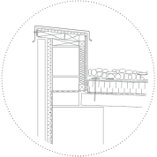
Parapet Wall
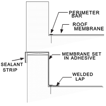 Cut and place the field membrane. The edge of the roof membrane should be flush with inside wall of the parapet.
- Install the perimeter mechanical fastening system (bars or plates and fasteners) in accordance with the manufacturer’s written instructions.
- Cut strips of membrane flashing. Strips must be wide enough to be carried down the outside face of the parapet, over the top of the parapet, down inside wall and out on to the roof at least 75 mm (3 in) past the perimeter fastening bar.
- Install the sealing tape (weather stripping) continuously along the outside face of the parapet. The bottom edge of the sealing strip should be flush with the outside bottom edge of the membrane flashing.
- Apply the adhesive to all surfaces to receive the membrane stripping. Take care not to get any glue on the lap area.
- Firmly press the flashing membrane into the glued area as per manufacturers recommendations.
- Weld the lap between the roof membrane and the flashing strip.
Walls
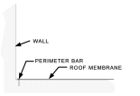 Cut, fit and position the field membrane. The edge of the roof membrane should be flush with the wall.
- Install the perimeter mechanical fastening system (bars or plates and fasteners) in accordance with the manufacturer’s written instructions.
- Cut strips of membrane flashing. Strips must be wide enough to extend up the wall to the desired height and on to the roof at least 75 mm (3 in) beyond the fastening bar.
- Apply the adhesive to the wall surface that will receive the membrane. Make sure no glue gets on to the lap area to be welded.
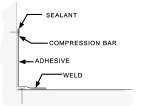 Firmly press the flashing strips into the glued area as per manufacturer’s recommendations.
- Apply bead of sealant between the top edge of the membrane and the wall.
- Weld the lap between the flashing strip and the roof membrane.
- Secure the top of the membrane to the wall with a metal of plastic termination (compression) bar fasted 300 mm (12 in) o.c.
Vents and Pipes
Many membrane manufacturers offer pre-moulded flashing for vent pipes, conduits, etc. When installing these, follow the manufacturer’s instructions carefully. Flashing for most roof penetrations can also be field fabricated.
When field flashing a vent pipe you will need two pieces of flashing membrane (typically glass fibre reinforced or unreinforced) cut to suit.
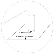 The first base flashing piece is cut to fit over the pipe and extend on to the roof a minimum of 150 mm (6 in) in all directions.
- Cut the base flashing piece to correct size with an opening slightly smaller than the pipe being flashed. Carefully warm the membrane at the penetration and stretch to form a raised edge that will be a tight fit to the pipe.
- Place the base flashing over the pipe and carefully push down on to the roof. The flashing should fit snugly over the pipe and when in place be turned up on the outside of the pipe about 12.7 to 25 mm (½ to 1 in).
- Weld the outside perimeter lap of the flashing piece on to the roof.
- Cut another piece of membrane equal to the height of the pipe, plus 50 mm (2 in) and wide enough to wrap completely around the pipe plus 75 mm (3 in).
- Apply adhesive to the pipe and/or the pipe in accordance with the manufacturer’s instructions. Turn up the bottom 25 mm (1 in) and wrap the membrane flashing tightly around the pipe pressing into the adhesive for a full bond. The bottom of the flashing is then gently warmed and stretched out onto the surface of the base flange piece approximately 25 mm (1 in).
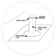 Weld the flashing strip up the vertical seam and along the lap on to the base flashing piece.
- Finish the top edge by installing a stainless-steel draw band, clamped tightly and caulked with an approved sealant as recommended by the membrane manufacturer.