The installation of modified bitumen membranes can be compared to the installation of a built-up roof membranes. Always ensure that the installation takes place in dry weather conditions. Ensure that any insulation laid is covered with a minimum completed, watertight membrane base sheet at the end of each work period.
There are generally four methods used for installing modified bitumen membranes: torch-on, hot mopped with asphalt, cold adhesive, or mechanically fastened. The proper application of modified bitumen membranes requires skill and care by the roofer. Application techniques must be altered to suit the weather and project conditions. The application of modified bitumen membranes, particularly during cold weather, may require special techniques to precondition materials to provide adequate flexibility and to facilitate the use of some adhesives, to ensure the proper bitumen temperature at the point of application. Some adhesives are not suited for use below temperatures that may occur during application and/or prior to full cure. By following proper procedures and exercising the recommended precautions, application can progress more efficiently and a higher quality of installation will be obtained.
The use of open flame and heated asphalt presents extreme hazard to personnel and property. Products applied by torching or mopping with hot asphalt should only be installed by skilled mechanics trained in their installation and proper safety procedures. Failure to follow the procedures as outlined or take the necessary precautions may result in serious injury and loss of property.
It is crucial that the roofing contractor understands the characteristics and limitations of the materials they are installing. Modified bitumen membranes are available with a variety of thicknesses, undercoatings, reinforcements, modifiers and surfacings. Different grades are also available for either summer or winter use. Only the appropriate grade for the conditions under which they are to be applied should be used.
SUMMARY OF COLD WEATHER PRECAUTIONS
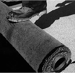
- During cold weather and where practical, store rolls of membrane in a dry and heated area.
- Storing the membrane in a heated area prior to use will preserve their flexibility.
- Bring rolls to the point of application only as they are needed.
- Where no heated storage area is available heat conditioning of the rolls with a torch at the point of application will improve their flexibility.
- When using hot asphalt for the application of the base and cap sheets, adhesion is much enhanced by applying heat simultaneously to the underside of the sheet and to the asphalt while unrolling, using a torch with a rapid sweeping motion. With lower temperatures, this may be the only practical solution other than full torching of the sheet.
Ideally, application should be scheduled so that there are no partially completed portions of the roof left exposed to the weather. If this is not practical, or application is interrupted by inclement weather, at least ensure that all base sheet laps, including perimeters, are properly sealed. Base flashing must be in place if there is any possibility of extended exposure. During this period while the base sheet is left exposed, ensure that all equipment traffic is prohibited.
By following these application procedures, the adhesion of the sheet will be enhanced, minimizing the occurrence of wrinkles and blisters.
5.2.2.1 Torch-On Application
Modified bitumen base sheet intended for torch application typically has a thin thermofusible film facing on the underside that is designed to melt and be absorbed by the underlying bitumen when heated by a torch at high temperatures. The modified bitumen beneath the film also softens and functions as the adhesive bonding the membrane to its substrate.
Modified bitumen cap sheets intended for torch application also typically have a thin a thermofusible film facing on the underside and are typically installed over base sheets having a thermofusible film facing on their top surface. When heated by the torch, the films melt and are absorbed by the modified bitumen and the modified bitumen beneath the films softens and fuses together, effectively creating a monolithic layer of modified bitumen between the reinforcement layers of the base and cap sheets.
The torching procedure is critical to membrane performance and application safety and is to be done by trained, skilled roofers only.
Note: A fire extinguisher is to be near the torching operation at all times.
 Torch applied modified bitumen membrane applications typically use vapour withdrawal propane cylinders with an appropriate torch kit. A valve or trigger to control the flame is located on the handle.
- Always ensure the couplings (regulator, hose, handle, head) are tight by testing as describe in this manual and in the manufacturer’s written instructions. Always use extreme caution when handling a torch, as the temperature of the flame can exceed 1093°C (2000°F).
- Larger torch heads with longer extension tubes are typically used when installing torch applied membrane sheets in the field of the roof and even larger heads may be required when doing torch applications in cold weather. Membrane flashing and other torch applied modified bitumen detail work is typically undertaken using a smaller torch head and a shorter extension tube for more focused flame control.
 Position the tip of the flame between 50 mm to 150 mm (2 in to 6 in) in front of the roll; in the area where the substrate and roll meet. The torch must be moved continuously across the width of the roll in order to achieve equal heating. As you heat the roll, a plastic film will disappear and a small bead of asphalt will appear. At this point, begin to unroll the membrane in a continuous motion.
- For field or the roof applications, do not walk on the heated membrane. To avoid this, use a roll puller (hook) to advance the roll toward the operator. This process requires the operator to always be walking backwards and, therefore, barricade all roof edges and roof openings. This method also enables the applicator to observe and control the heat he applies to the roll and substrate surfaces.
- For torch applied modified bitumen membrane flashing applications, apply pressure to the surfaces to ensure complete contact and avoid gaps and voids, particularly at side and end laps.
- Avoid overheating the sheet. Signs which indicate overheating are:
- The plastic film starts to melt on the top of the roll.
- Granules begin to sink into the membrane.
- The bitumen melts away, exposing the reinforcement.
- Waves become visible on the laid membrane.
The use of open flame and heated asphalt presents extreme hazard to personnel and property. Products applied by torching or mopping with hot asphalt should only be installed by skilled mechanics trained in their installation and proper safety procedures. Failure to follow the procedures as outlined or take the necessary precautions may result in serious injury and loss of property.
When installing the cap sheet, ensure that the base sheet and cap sheet roll are heated simultaneously.
Know the nature of the product you are going to torch such as thickness, reinforcement, under-face (sanded or thermofusible plastic film). Know the substrate you are torching to (e.g. wood, concrete or another membrane).
The torching application rate will vary with the wind and weather. It is slower under cold and humid conditions than when it is warm and dry. This speed could change from day to day as well as during the day. To set your speed daily, practice on the first roll you are putting down. Heat roll for a few centimetres, stop, pull the roll back, check the uniformity of the weld, and set your pace according to your result. Frequently check weld integrity during the course of the day. Note that gas consumption rates will vary related to these elements.
As noted above, the movement of the torch should be a continuous to and from motion allowing the flame to cover the entire width of the membrane without burning the side of the adjacent sheet already installed. Do not point the flame beneath the sheet (this could entrap air). For best results, make sure that there is a continuous bead of molten modified bitumen at the junction of the roll and the substrate. When in doubt, stop, roll- back, stringy filaments of modified bitumen should be present on the full width of the roll.
End Lap And Side Lap Sealing
End laps are areas of possible infiltration of water due to an excessive thickness of membrane causing a void. The potential for the formation of this void is reduced by removing a triangular piece of the underlying membrane selvage which allows the bitumen at the face of the overlapping roll to flow along the diagonal edge.
Procedure
- Cut off the corner piece of the selvage edge at the end lap that will be covered by the next roll.
- Make sure you cut off the corner when membrane in unrolled dry before torching in place.
- Apply this rule for base and cap sheet membranes as well as for flashing details.
Granule Embedment
Granule embedment or the preparation of the selvage where the cap sheet will overlap on the mineral surface is MANDATORY. This operation is necessary for good adhesion at these critical areas and is required at both end laps and at side laps where granules are present.
By embedding the granules there will be adhesion to bitumen. If this is not done, the adhesion maybe inadequate and could cause delamination and/or moisture penetration.
To embed the granules, soften the bitumen by heating the mineral surface with the torch. When the granules start to sink into the bitumen, stop torching and, with a hot trowel, embed the granules in the bitumen. A “hot” trowel will slide easily and prevent granules from sticking to the trowel. It’s important to trowel in the granules by sliding the trowel on the surface and not to scrape off granules and bitumen. Granular end laps should be prepared well before the following roll approaches for bonding to the end lap. If granule embedment is delayed until the next roll is within 600 mm (24 in) of the end lap, the rolled material will overheat from residual heat generated from the embedding process.
Typically, side laps of granular cap sheets have a selvage which has a thermofusable film surface rather than granules and can be fully bonded with minimal visible modified bitumen bleed-out at the edge. A visible bead of bitumen is an immediate sign that the lap is securely sealed. Any bleed out in excess of this amount can be covered with matching granules set in reheated bitumen.
5.2.2.2 Hot Mopping Application
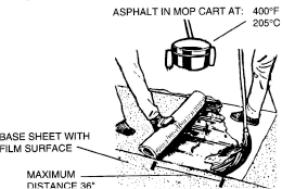
 Some types of modified bitumen membranes may be applied with a mopping of hot asphalt in the same general manner as installing a built-up roof system, however the EVT concept does not apply to hot- mopped polymer-modified bitumen membranes. Rather, the bitumen must be at an elevated temperature at the point of application sufficient to penetrate the sanded surfacing and bond to the modified bitumen of the membrane sheet.
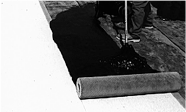
Thus, do not apply the asphalt more than 900 mm (3 ft) ahead of the roll to prevent cooling of the bitumen surface prior to bringing the membrane into contact with the bitumen.
Apply at a rate of 1.2 to 1.5 kg/m² (25 to 30 lb/square). Ensure the temperature of the asphalt is sufficient to provide adequate bonding. The application temperature of the asphalt must be at a minimum of 220°C (430° F) or as recommended by the membrane manufacturer. Application of membranes at lower temperatures may require additional measures to ensure proper bond, such as applying additional heat to the bitumen surface and the face of the roll with a torch using a sweeping motion as the roll is advanced into the bitumen. Obviously appropriate care must be taken when using a torch in this way.
Use the type of asphalt appropriate to the slope of the roof deck. Do not use low melt asphalt (Type 1) to apply modified bitumen membranes and follow manufacturers recommendations for the project location and roof slope to identify the appropriate asphalt type.
 High asphalt temperatures are essential for adequate adhesion in the application of SBS modified membranes. In the winter the asphalt should be as hot as safely possible to compensate for the more rapid rate of cooling. Failure to have the bitumen at a required temperature will result in poor membrane adhesion. In no case should the maximum temperature limit exceed the bitumen’s flash point.
Proper insulation of all bitumen handling equipment is required to keep bitumen hot in cold weather. Insulation of the equipment is equally vital for fuel conservation and will result in savings in make-ready time. The use of insulated tank trucks and rooftop equipment for transporting bitumen such as hot luggers and mop buckets is recommended. Bitumen lines from the kettle to the roof should also be insulated. This is especially important when bitumen is being transported over long distances.
Mop the granule-surfaced cap sheet carefully to avoid excessive asphalt seeping from the laps. If excessive asphalt seeps from the laps, embed loose granules in the hot asphalt.
The procedure to complete a 2-ply modified bitumen membrane system involves the following steps:
- Applying the field base sheet.
- Applying the base membrane flashing.
- Install flashing for roof penetrations and roof anchors and drip flashings.
- Applying the cap sheet.
1. Applying the Field Base Sheet
Base sheet membranes installed in the field of the roof can be applied mechanically fastened, torch-on, hot mopped, cold adhesive adhered, or are pressure sensitive (self- adhered). Always begin to install the membrane at the lowest edge or point of the roof. On a sloped roof deck, the first row of membrane is to run horizontally along the roof edge. The remaining rows will be installed vertically up the slope and are perpendicular to the first row. On roof decks sloped to internal roof drains, unroll the first row of membrane with the roll edge centered through the roof drain penetrations. The remaining rows will run parallel to the first row working upslope from the drain. Centering the base sheet roll edge at the drain allows the side lap of the cap sheet to avoid the roof drain clamping ring. Terminate the field base sheet at the top of the cant, at the base of the curb or at the perimeter as appropriate.
Prepare the membrane for installation in each and all rows in the following manner:
-
- Roll out the membrane to half the length of the row. Pull the unrolled material tight and fit in the desired position.
- Backroll the roll and work from the center of the row out to the edges.
- Mechanically secure the roll with plates and fasteners, or torch adhere, or adhere with hot asphalt or cold applied adhesive, or apply the pressure sensitive membrane to the pepared substrate surface in strict accordance with the manufacturer’s written instructions.
Self-Adhering (Pressure Sensitive) Base Sheet Membrane Applications
Some base sheets are self-adhering membrane. These products are coated on the bottom with specially formulated modified asphalt that remains tacky in mild temperatures. To prevent the rolls from sticking together, a release paper is factory applied to the bottom of the roll. This release paper must be peeled off to facilitate bonding of the sheet to its substrate. To apply a self-adhering sheet:
-
- Peel off the backing wrapper as you unroll and position the membrane.
- For some membranes, the recommended method is to advance the roll by pulling the backing from beneath the roll in the direction that the roll is being advanced.
- For other membranes, the backing is split near the center of the roll and the recommended installation method is to position the roll and hold in place while removing the backing from one side and then the other by pulling it out perpendicular to the length of the roll.
- Press each roll into place with a heavy, weighted roller to ensure complete adhesion and eliminate voids. A 34 kg (75 lb) segmented steel roller is typically used for this purpose. Rolling is usually done in both directions and in the sequence recommended by the membrane manufacturer to give optimum result.
- All misaligned rolls must be cut off and reset. Cut out and patch all fish mouths, wrinkles, and buckles.
- Ensure that all side laps are overlapped a minimum of 75 mm (3 in), and end laps a minimum of 150 mm (6 in). Particular care is taken when rolling side and end laps to ensure complete adhesion.
- Peel off the backing wrapper as you unroll and position the membrane.
2. Applying the Base Membrane Flashing
Base membrane flashings are installed to all parapets, curbs and sidewalls. The base sheet flashings are typically installed after the field base sheet membrane and prior to the installation of the field cap sheet membrane.
Membrane flashing base sheets are installed perpendicular to the roof edge or curb. They may be cut from the same field base sheet membrane material or may be a similar material that is designed to have a different but compatible application technique. Modified bitumen membrane base sheet flashings are typically cut from the end of the 1 m (39 in) wide roll at a length sufficient to extend 100 mm (4 in) minimum onto deck (beyond the toe of the cant strip if any) [200 mm (8 in) minimum in some jurisdictions and/or for some application types] and up the wall a minimum of 200 mm (8 in) or over the top of parapet or curb. These sheets are installed to the deck first, then bonded up the wall. They are usually bonded with a torch, but sometimes Type 3 asphalt is used.
Ensure that the membrane flashing base sheet is pressed firmly in place. Pressure sensitive and cold adhered membrane flashing sheet applications must be pressed into full contact using an appropriate hand roller. Hot applied membrane flashing sheet applications should be pressed into place using an appropriate flat float type tool. The 1 m (39 in) wide strips of membrane flashing are set to overlap the factory selvage of the adjacent strip by at least 75 mm (3 in), similar to membrane field base sheet applications. Stagger the base sheet flashings a minimum of 100 mm (4 in) with the underlying field base sheet to avoid excessive thickness.
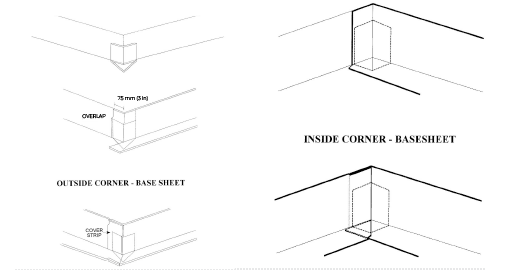
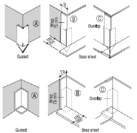
Gussets
“Gussets” are required at all inside and outside corners of membrane flashings for all types of membrane flashings applications. The gussets provide a seal where the corners of the membrane flashing plies have to be cut, preventing the penetration of heat and flame during torch applied membrane flashing applications and moisture penetration over the installed life of the membrane flashings. The gussets are to be installed in accordance with the recommendations of the modified bitumen membrane manufacturer. At cant strips, the gussets are to either be double ended or are to be installed at the corners at both the base and top of the cant strip.
The following illustrations illustrate the role of the gusset in sealing the potential opening at the corner of the flashing at typical inside and outside corners. Gussets are sometimes installed beneath the membrane flashing base sheet or over the membrane flashing base sheet and beneath the membrane flashing cap sheet, depending on the method of installation for these components. Consult the membrane manufacturers written instructions for the correct location.
3. Install flashing for roof penetrations and roof anchors and drip flashings
All flanges of roof penetrations, roof anchors and drip flashings that will be in contact with the membrane need to be cleaned and primed. The flanges of roof anchors should be 125 mm (5 in) larger than the pipe or drain bowl. Drip edge flashing are typically manufactured with a 100 mm (4 in) minimum width flange and a gravel stop lip equal to 2 layers of membrane 6 mm (1/4 in). Carefully flash off any thermofusible film from the top side of the field base sheet using a hot air gun or torch. Coat the underside of flanges with compatible modified bitumen mastic and fasten in place. Over the flange, bond a 275 mm (11 in) wide layer of reinforcing membrane strip insuring that it is completely sealed to both the flange and base membrane.
4. Applying the Field Cap Sheet
The cap sheets are installed in a manner similar to the base sheets.
-
- Begin by unrolling the membrane along the low spot and position in place. Align cap sheet parallel to underlying base sheet. Offset cap sheet side laps a minimum of 300 mm (12 in) and end laps a minimum of 450 mm (18 in) from those of the base sheet. For installations starting at the roof drain, position the first cap sheet so that the side laps will not occur under the roof drain clamping ring. Under no circumstances superimpose the laps of the cap sheet over those of the base sheet. Carry membrane field cap sheet to the bottom edge of the cant or the base of the curb in the absence of a cant strip.
- Backroll the membrane to allow you to work out from the center in both directions. Ensure the cap sheet is laid smooth and is free of air pockets and wrinkles.
- Cap sheets may be bonded to the membrane base sheet using appropriate torch adhered methods, adhered with hot asphalt or cold applied adhesive, or pressure sensitive membrane may be applied to the prepared substrate surface in strict accordance with the manufacturer’s written instructions. The membrane sidelaps should be a minimum of 75 mm (3 in) and endlaps 150 mm (6 in). No more than a 6 mm (1/4 in) of asphalt should seep out the sidelaps when torching.
End Laps
 When sealing end laps with a granular surface (or side laps in the absence of a factory selvage), the bottom layer must be prepared. For torch adhered cap sheet applications, this is done by heating the 150 mm (6 in) wide area that is to receive the next membrane. Heat with a torch and when the membrane begins to soften, use a blunt nosed trowel to press the granules down into the membrane. This should provide you with a plain asphalt surface.
Before bonding the bottom sheet, for all applications, the exposed corner must be cut at a slight taper to allow asphalt to flow out and provide a longer tapered surface for proper sealing.
5. Applying the Cap Membrane Flashing
Cap flashing is installed over the base flashing and extending onto the field cap sheet. The cap sheet flashings may be installed using the same method as the field membrane on alternate, compatible installation method where appropriate.
As with membrane flashing base sheets, membrane cap sheet flashings are installed perpendicular to the roof edge or curb. They may be are cut from the same field cap sheet membrane material or may be a similar material that is designed to have a different but compatible application technique. Modified bitumen membrane cap sheet flashings are typically cut from the end of the 1 m (39 in) wide roll at a length sufficient to extend 150 mm (6 in) minimum onto deck (beyond the toe of the cant strip if any) and up the wall a minimum of 200 mm (8 in) or over the top of parapet or curb.
Ensure that the membrane flashing cap sheet is pressed firmly in place. Pressure sensitive and cold adhered membrane flashing sheet applications must be pressed into full contact using an appropriate hand roller. Hot applied membrane flashing sheet applications should be pressed into place using an appropriate flat float type tool. The 1 m (39 in) wide strips of membrane flashing are set to overlap the factory selvage of the adjacent strip by at least 75 mm (3 in), similar to membrane field base sheet applications. Strips of membrane flashing should overlap the factory selvage of the adjacent strip by at least 75 mm (3 in). Stagger the cap sheet flashings 300 mm to 450 mm (12 in to 18 in) with those of the base sheet flashings a minimum of 100 mm (4 in) with the underlying field cap sheet to avoid excessive thickness.
Generally, the application of membrane cap sheet flashings may be summarized as follows:
- Cut the strips of membrane cap sheet flashings from the end of a roll of appropriate cap sheet materials long enough to extend 150 mm (6 in) onto deck over cap sheet and extend up the wall the desired height; a minimum of 200 mm (8 in) above the surface of the roof or over the top of parapet.
- Install a chalk line on the field cap sheet, 150 mm (6 in) in from the toe of the cant or the base of the curb to use as a guideline.
- When installing flashing on a granular cap sheet, this 150 mm (6 in) wide area must be prepared like an end lap. Where the membrane flashing cap sheet is to be torched or heat sealed to the field cap sheet, heat the surface of the field cap sheet with a torch or hot air gun and with a trowel press the granules into the membrane, bringing the bitumen to the surface.
- Install flashing from the deck up the wall using the appropriate technique for the material being applied. Where appropriate, heat seal side laps and the seal between the toe of the membrane flashing cap sheet and the field cap sheet with a torch or hot air gun. Ensure that the membrane flashing cap sheet is pressed firmly in place with a roller or float.
- Continue to lay succeeding layers of flashing in the same manner with a minimum 75 mm (3 in) sidelap.
- After completion, check that all seams are completely bonded. Install any required metal cap or counter flashing using good roofing practice.
For cap sheet membrane flashings that are torched-on, ensure that both surfaces are heated for a complete bond. Always be careful to not overheat the membranes.