3.1.4.1 Expansion Joints
Expansion joints are structural joints in a building that are required to control the stresses in the structure due to changes in dimensions, changes in temperature and sometimes moisture. You can tell if a joint is an expansion joint by the fact that it runs through the entire structure, starting at the foundation and continuing up the walls, through each floor and finally the roof. It is the responsibility of the structural engineer or designer to determine where the expansion joint should be placed, and the size of the opening.
Constructing Joints
- Roof expansion joints are constructed so that some movement of separate areas of the roof system can occur without damaging the membrane.
- Expansion joints must be constructed at each structural expansion joint on the deck;
Joints are typically constructed of wood planking and cant strips. It is the roofer’s responsibility to ensure that it is properly flashed and roofed in, using only the materials specified that will accommodate the expected movement. Joints must always be constructed so that they extend at least 200 mm (8 in) above the finished roof surface.
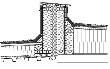
There are four steps for constructing an expansion joint as follows:
- Fasten the base of the expansion joint to the side of the joint to form an L shape.
Butt the two sides of the expansion joint together. Notice that the two sides of the expansion joint are separated by a layer of insulation. This must be material flexible enough to return to its original shape after having been squeezed by the repeated closing and opening of the joint. Most joints will also have a flexible seal spanning the joint at the deck. This is to prevent air leakage through the joint and to prevent the compressible insulation from falling through when the joint opens. In addition, it may also be required as a firestop. Never fasten the two sides of the expansion joint together as they must be free to move independently. - Cut the tops of the two sides of the expansion joint to an angle. This will provide positive drainage.
- In BUR systems, install a cant strip along both sides of the expansion joint.
- Lay expansion joints continuously across the roof.
3.1.4.2 Roof Area Dividers
Roof area dividers serve a number of purposes in a roofing system including:
- Separate a new roof system from an existing roof system where there is not a change in roof deck direction or material.
- Separate adjacent roof areas with different thicknesses of insulation.
- Divide large roof areas into manageable sections. This is especially important in reroofing. By dividing the roof, sections can be replaced or repaired instead of the whole roof, and tie-ins become much easier.
- Prevent water from leaks from migrating through the entire roof. If a leak occurs in one area, the water cut-off provided by the area divider will stop moisture from entering a neighbouring section.
Roof area dividers should be constructed in each of the following locations:
- At each change in direction of the roof deck.
- At each point where two different types of decks meet (i.e. if a deck is half wood and half steel).
- At points where the building changes direction.
- At points where a new addition is joined to an existing building (tie-in).
- At locations where it is necessary to reduce built-up roof (BUR) membrane into 45 m x 45 m (150 ft x 150 ft) sections (maximum).
Roof area dividers are usually constructed of wood planking and cant strips and like expansion joints, must extend at least 200 mm (8 in) above the finished roof surface.
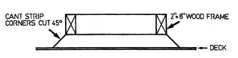
There are two major steps in the procedure for constructing a roof area divider. These are:

- Fasten the two 50 mm x 200 mm (2 in x 8 in) wood planks together to form an I shape.
- In BUR roofs, install a cant strip along both sides of the roof divider.
Roof area dividers should not be confused with membrane control joints. Membrane control joints (where the membrane has been cut to allow the membrane to move) have been shown to do more harm than good and are not recommended.
3.1.4.3 Curbs
Roof curbs are raised members that are used to support roof penetrations, mechanical equipment, skylights and roof hatches. Curbs must be constructed for all types of roof openings and on both insulated and un-insulated decks.
Constructing Curbs on Uninsulated Decks (BUR)
The curbs constructed on un-insulated decks are 50 mm x 200 mm (2 in x 8 in) square boxes. There are 3 major steps in the procedure for constructing a curb on an uninsulated deck as follows:
- Fasten the curb to the deck.
- Install a wood or fibre cant strip on all sides of the curb.
- Cut the corners of the cant strip at 45° angles to ensure a tight fit.
Constructing Curbs on Un-insulated Decks (Single Plies)
- Fasten the curb to the deck.
Constructing Curbs on Insulated Decks (BUR)
The curbs constructed on insulated decks are normally 50 x 200 mm (2 in x 8 in) square boxes. The major steps in the procedure for constructing a curb on an insulated deck as follows:
- Attach a 50 mm x 150 mm (2 in x 6 in) base flange to the bottom of the curb so that it rests on the deck.
- If the curb itself is to be insulated, apply the specified insulation over the sides of the curb.
- Install a wood or fibre cant strip on all sides of the curb.
- Cut the corners of the cant strip at 45° angles to ensure a tight fit.

Constructing Curbs on Insulated Decks (Single Plies)
- Attach a 50 mm x 150 mm (2 in x 6 in) base flange to the bottom of the curb so that it
rests on the deck. - If the curb itself is to be insulated, apply the specified insulation over the sides of the curb.
- Install a wood blocking to suit height of insulation on all sides of the curb.