Perimeter Edge Flashing and Wind Resistance
June 2007
According to the insurance industry’s Institute for Catastrophic Loss Reduction, damage due to hurricanes and other windstorm events has increased dramatically in recent years, incurring losses of life and property around the world. With the exception of a few abnormally severe storms, most of Canada was considered immune to the devastation caused by the major wind events that routinely rip through southern and midwestern regions of the U.S. This is no longer the case. Just in the past few years, severe storm systems have battered all regions of Canada, from the Atlantic through to the Pacific coasts. Early in 2006, winds gusting to more than 80 km/h tore through Atlantic Canada. Downed power lines in New Brunswick left an estimated 200,000 business and homes without electricity. More recently, Alberta experienced a storm with shearing gusts and sustained winds clocked as high as 120 km/h that damaged homes, pushed transport trucks off highways and spread debris throughout southern Alberta. Early last November, a major storm swept through British Columbia’s lower mainland blowing roofs off of buildings and bringing down hydro lines. Damaging winds in excess of 100 km/h toppled a four storey steel frame building under construction.
Environment Canada has issued warnings advising that severe windstorm activity is on the upswing and we should expect many more similar storms in the decades to come. The roofing industry has reacted to the rising frequency and severity of the increased major wind events in several ways. Major research organizations, such as National Research Council’s Institute for Research in Construction (NRCC/IRC) and numerous universities have embarked on research designed to make our buildings and their components more wind resistant. Roofing systems approval and certification organizations, together with building code authorities, have changed their wind resistance requirements. In the aftermath of catastrophic property losses suffered during the 2005 hurricane season, FM Global revised its1-29 Loss Prevention Data Sheet in January 2006, significantly increasing the corner and perimeter attachment for fully adhered built-up, modified bitumen, and single ply membrane over insulation mechanically fastened to steel decks.
One of the most important revisions to the National Building Code of Canada (NBCC) was the change of the return period to determine the uplift pressure from 1 in 10 years to 1 in 50 years. Manufacturers have been conducting their own in-house research and development to enhance the wind resistance of their products and systems. All this activity reflects the expectation by the industry that major wind events will become more frequent and severe.
As a result of increased awareness of the need to build roofs with the necessary uplift resistance to remain in place during strong winds, most design professionals now pay close attention to the attachment of the various roof components, including the membrane cover and insulation. However the role of the perimeter flashings in the wind performance of the roof is often overlooked. The roof edge is one of the most important components of any roofing system. According to FM Global, the worlds leading commercial and industrial property insurer, the majority of roofing cover failures resulting from windstorms involve improperly designed or constructed perimeter flashings. These failures occur when wind suction or pressure works on the metal flashing fascia and the wood nailer and cant assemblies. Once the flashings have been displaced, or torn away, the roof covering is vulnerable and may be easily peeled back, leaving the deck and the building interior unprotected.
It doesn’t take hurricane force winds to rip up a roof edge. The pressure acting on perimeters and corners of the roof can be as much as three times greater than those that occur in the field of the roof. Recently, the Roofing Industry Committee on Weather Issues (RICOWI), reported on the roof related damage in Florida from the 2004 hurricanes. They found that most of the damage was caused by the failure at the perimeter. According to the study’s authors, the membrane attachment to the deck could not resist the loads created when the perimeter securement failed, leading to a progressive peeling and loss of the membrane. Known as the “zipper effect”, once the edge securement fails, decreasingly less force is needed to peel away the roof cover.
The wind pressures at a building’s perimeter depend on a variety of factors. Many are related to the features of the building itself, including geographic location, building height and geometry, exposure and surrounding terrain. Still others are specific to the design and materials used in the construction of the perimeter flashings. The variables here include the type of metal, gauge thickness, profile, fastener type, location and density. One thing is clear, and that is that the edge flashings, irrespective of the material or detail, must be solidly anchored to the supporting structure to prevent wind displacement and blow-off. Resistance to blow-off depends not only on the way the flashing is attached at the perimeter, but also on the integrity of the substrate to which it is fastened. This is normally accomplished by providing wood cants, nailers, or other kinds of blocking to which the metal and membrane flashings can be secured.
There are several design standards for edge securement available to designers and specifiers. These include the American National Standards Institute (ANSI) Wind Design Standard for Edge Systems Used with Low Slope Roofing Systems (ANSI/SPRI ES-1-98), FM Global’s Loss Prevention Data Sheet 1-49: Perimeter Flashing, and the Sheet Metal & Air Conditioning Contractors National Association’s (SMACNA) Architectural Sheet Metal Manual. These all prov ide detailed information on sheet metal type and gauges, cleat gauge, and fastener placement. The first two provide guidance to flashing design to meet specific wind uplift forces for a particular build ing based on design variables such as location, building height, surrounding terrain and geometry. They also provide guidance with respect to attachment of nailers. Both FM’s 1-49 and the ANSI/SPRI design standards recommend that nailers should be constructed of a minimum of 38 mm wood members and that they be anchored to steel decks and concrete blocks with steel bolts.
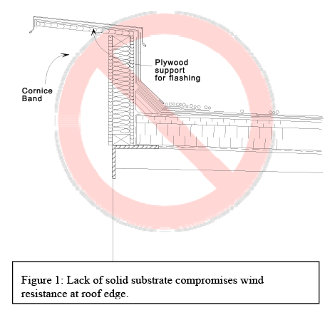
It is imperative that designers carefully consider the wind resistance of the roof edge together with that of the field of the roof. In many cases, attempts to satisfy aesthetic requirements have compromised the wind performance of the roof assembly. A typical example can be found in the increased use of architectural reliefs known as EIFS cornice bands around roof edges. These bands typically consist of a polymer modified stucco applied to polystyrene foam moulded in various shapes.
As attractive as these bands are, they present a problem for the roofing contactor who is responsible for adequately securing the edge system. In many applications, only a thin layer of plywood acts as the substrate to which the coping is attached (see Figure 1). It is evident that this detail will not provide sufficient resistance to blow-off, even under moderate wind conditions. Roof designers must realize that marginal attachment at the roof perimeter may jeopardize the wind resistance of the entire roof system and can result in a catastrophic loss of the roof cover.
The opinions expressed herein are those of the CRCA National Technical Committee. These Technical Bulletins are circulated for the purpose of bringing roofing information to the attention of the reader. The data, commentary, opinions and conclusions, if any, are not intended to provide the reader with conclusive technical advice and the reader should not act only on the roofing information contained in these Technical Bulletins without seeking specific professional, engineering or architectural advice. Neither the CRCA nor any of its officers, directors, members or employees assumes any responsibility for any of the roofing information contained herein or the consequences of any interpretation which the reader may take from such information.